


But before we look at the monitor, let's see what happens to our electronics without it and in what cases. And then we'll see what it's for...
Many electrical and electronic components are useful for the protection of our devices and especially the expensive ones and those with electronic parts of devices eg: Refrigerator, TV, computer, washing machine, air conditioner and others...

To say that we will have the maximum protection, we also need enough money! Despite all this, we will notice in many cases with every protection measure we use, more and more some "strange" current will "slip" and take away some of our electronic devices.
But what happens and our devices get burned or destroyed by the current?
We will notice that the ideal operating voltage is indicated on all devices on their label. And why do we say ideal? Because the trend is almost never constant. That is, we will see her going up and down from the ... heights to the ... depths!! While this device works well at specific volts without voltage fluctuations.
We will notice that all things or living things on earth have the same symptoms! We hear hypertension and hypotension in medicine too!!
And it's exactly the same thing! The human is programmed to work with a pressure of 12/8 when one of these two values cross the limits up or down we have a terrible issue. Especially when the pressures are out of bounds for a long time and we don't know it, at some point the stroke comes and the "machine" needs repair or kaput!! But there are also people who understand it from some early symptoms, so they improve it!!
Let's leave medicine, which often resembles electrical engineering, and go to the subject again...
Ideal trend
All single-phase devices manufactured for our country, for some years now, have been manufactured with an ideal operating voltage of 230 volts. This is the promised voltage provided by DEDDIE per phase. What happens now if the trend crosses this limit up or down?
Simple, as long as we do the operations with Ohm's law. We will notice that as the voltage drops, the amperes rise (so more intensity). What does more intensity mean? It means an increase in temperature and current within the electronic circuits. This is the slow death of our devices!!
If the voltage drops a little below or rises a little above the ideal 230V, it does not mean that the devices are burning. They work at 210 and at 200 and at….190 and …… hey! From 210 to 250 theoretically there is no problem. When these values are exceeded, problems begin. We will hear the refrigerator struggling and little by little the rest of the devices will burn boards. Air conditioners also pull very hard with fluctuations….
A problematic trend will therefore create a slow death for us devices. The lower voltage we have, the faster the devices will deliver spirit.
If you look at the back of the PPC bill you will see that they OPTIONALLY recommend the use of surge or undervoltage protection devices. Because PPC does not provide what it promises, the consumer again has to incur costs for his protection.
Only problem in phases cause death in our devices?
No! The most important problem is the interruption of the neutral conductor! It is the worst thing that can happen to an electrical installation and it is quite a frequent phenomenon throughout Greece and especially where the TN protection system prevails . So in the event of neutral interruption we have INSTANT device death!!
Good then. And what do we do about it all? Is there a way to protect ourselves?
There are many ways to protect. If we use all means we need a lot of money, especially if we go for reliable solutions and not cheap parts of the basket.
The main ways are: Lightning Protection, Over Voltage Protection, Voltage Stabilizer, UPS, Voltage Monitor, Temperature Monitor, Arc Detector and many more. So you understand that to buy all this, we need a lot of money.
How do we choose a protection method from all of the above?
Since I am mainly addressing the simple consumer and not an industrial facility (most people have taken their measures there) we must first calculate what devices we have, how much it costs to replace them and from there we choose protection. So, in a simple installation where the simple consumer "pains" is to protect the following: Computer, TV, stereo (if any) refrigerator, air conditioner. These are the main ones. So we need to know that with a big voltage drop these devices really struggle! But we don't know this, or someone experienced will understand it, seeing some "signs" in the installation such as the flickering of the lights (if they are led, the lamps will blink or burn often), noise in the refrigerator or air conditioner, and others.
So we calculate what the slow death (which applies to all devices) and the instantaneous death that happens in special cases, but often and especially in unmaintained networks such as island ones (eg polar voltage due to return currents in a TN network) will cost us.
So the voltage monitor will show us the problem very early! What do we mean? That the supervisor, depending on what values we have set it to, will cut our electricity supply. Whether these are momentary voltage drops or permanent.
Monitors are of various types and have various settings. An ideal and economical monitor that ALWAYS saves us from disasters is the phase and neutral voltage monitor! Be careful here, many years ago, whoever installed a monitor, installed a single-phase or three-phase voltage monitor. However, this is not useful in mainly TN networks. Because there we encounter more neutral interruptions, so we need a supervisor who will also supervise neutral!! It is a few euros more expensive but it literally saves our devices.
How is the voltage monitor installed? Is it a difficult process?
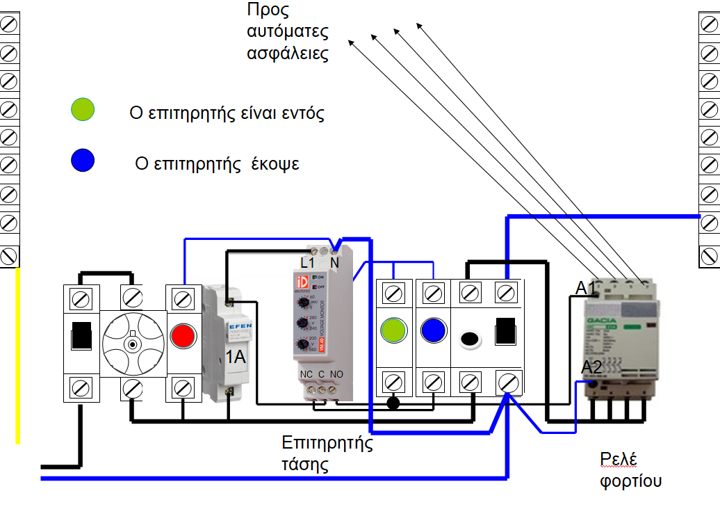
It is not at all difficult to install. As long as there is the required space in the table. See drawing below...

What do we need to install the monitor?
Basically a phase and neutral monitor. If the installation is three-phase, we want something like this...

Automatic fuses from 2 A – 6 A
A three-phase or single-phase power relay (depending on the installation).
It is usually a good idea not to load the monitor directly with the loads and to use it as an auxiliary circuit, so using a power relay that will accept all the loads is essential.
After it is installed, we start the setup. We will see that it has some buttons on it...
In one we state how much voltage drop we want the monitor to break
In the next, at how much overvoltage we want it to break
In the next, how long do we want it to stop!! That is, if the drop or surge lasts for a few seconds, we can choose not to interrupt. And the interruption should ONLY be done when the voltage drop lasts long enough, at which point it will cause a problem.
Disadvantages of voltage monitor
The disadvantages of the voltage monitor are …one! Every time he "sees" a problem, then....the power goes out in our house! This is a little spastic especially when we are snuggled up on the sofa and enjoying a movie in our home cinema or we are at a party and suddenly.... darkness!! But if we think about the benefits and that our good 50'' TV was spared, then we say... let the old one go!
If we are now a little more "well-off" we can add a voltage stabilizer to the installation. In this case and with small fluctuations we will notice that the overseer will fall more sparsely!
If we want even more autonomy and not instant interruption, then we can add a UPS which will power our sensitive devices. So eventually (despite all the stabilizer) the power will drop, but the UPS will give us the time we need to shut down our devices in absolute safety.
We can have socket protectors anyway. These are economical and work both in voltage drops and momentary overvoltages.
I'm not interested in a monitor for the whole house. Can I ONLY put on my sensitive devices?
Of course we can. We can select the lines that include the sensitive devices and only those to be checked by the voltage monitor. Ohmic resistors are not damaged by fluctuations anyway.
But again, especially in 2018, we will notice that even the electric stove now has an electronic cart. Our LED lamps are all electronic and sensitive to fluctuations. In general, be aware that: Any electrical device that contains electronics, has an issue with voltage fluctuations.
Conclusion: The most important component in an electrical installation after the leakage relay, the phase and neutral monitor literally SAVES everything in a home - office - building - factory.
VOLTAGE MONITOR CONNECTION

The PPC on the back of each of its bills writes: Small or large changes in the supply voltage are unavoidable since they can be due to natural phenomena etc. etc. And below it continues: Customers can optionally install suitable protective devices to prevent damage or the occurrence of anomalies in the operation of their devices. (And of course it's like he's saying, I warned you not to ask me for change for the burnt TV.)
Voltage fluctuations are a frequent phenomenon observed in electricity networks. The electrical devices we have in our house have tolerance to small fluctuations and thus no problem is created. But there are times when the voltage sinks to values below 210V or even jumps to 260V and above. The voltage monitor is a useful component to protect an installation from dangerous disturbances.
Voltage fluctuations are a frequent phenomenon observed in electricity networks. The voltage that reaches the electrical panel of our house is constant at 230V. But this only applies in theory or better "under ideal conditions". In practice, the voltage that ends up on the panel of our house and from there on our devices takes various values around the nominal one, i.e. 230V. So if we did a voltage measurement at any time of the day, we would most likely get a value like 220V, 225V or 235V. The electrical devices we have in our home are tolerant to these fluctuations and thus no problem is created. But there are moments when the voltage sinks to values below 210V or even jumps to 260V.
Due to overloading of a network, which is usually caused by increased power demand, a voltage drop occurs which can reach very low values and last either a few milliseconds (less than a second – 1000 milliseconds = 1 second) or an hour. This voltage drop results in wear and tear on a home's appliances. So we will see the lighting "flickering" or "weakening" illuminating much less than normal, the oven not reaching the temperatures it should and, in general, all the electrical devices not reaching the performances they should. If the voltage drop lasts a few seconds there is most likely no problem at all. But if it reaches a duration of one minute and exceeds it, then the devices that will be used at that time will have a problem. Besides,
However, the opposite also happens. Sometimes due to weather phenomena (lightning) and other times due to the supply from the network we have overvoltage, i.e. the voltage is much higher than the permissible limits. The result of an overvoltage is to "burn" a device. Lightnings cause a momentary and sharp rise in voltage, which ultimately the TV or computer may not be able to "stand" without of course this being absolute. But if the overvoltage is caused by the network itself and lasts longer, then the chances of losing one or more devices are greatly increased.
The voltage monitor is a rail material just like the rest that make up our electrical panel. The phase conductor passes through the monitor before it reaches to supply our electrical installation and thus it constantly checks the voltage value. In the monitor settings we select the upper and lower permissible limit as well as the reaction time. Thus, when the voltage takes values outside the set limits, the monitor "counts down" according to the time we have given it (usually a few seconds). If the voltage is still outside the limits, the supervisor "cuts" the supply to the installation to protect the devices. When the voltage returns to normal values then the supervisor "turns on" the power and everything starts working normally again.
I think we all care to protect air conditioners, refrigerators, TVs, computers, etc.
So instead of spending money on safety multi-sockets, it is better to install a voltage monitor in the installation's electrical panel and you are done with the problem once and for all, you also protect your inverter air conditioners which in overvoltage would have a serious possibility of being destroyed (in undervoltage they have their own security) .
Also to say that the voltage monitor is a good solution for protection against neutral interruption
The voltage monitor is an electronic device that checks the voltage in the electrical network of the installation for undervoltage, overvoltage
There are single-phase monitors (phase + neutral) and three-phase with control (3-phase or 3-phase + neutral).
The monitor has two contacts on it, a normal open and a normal close with which we can control the circuit through a power relay.

The supervisor checks the voltage and depending on the overvoltage or undervoltage that we have set it to excite or de-energize the power relay.
In this way, it interrupts the operation of the installation in the event of a voltage error
In the photo below we see a three-phase voltage monitor and next to it a rail load relay
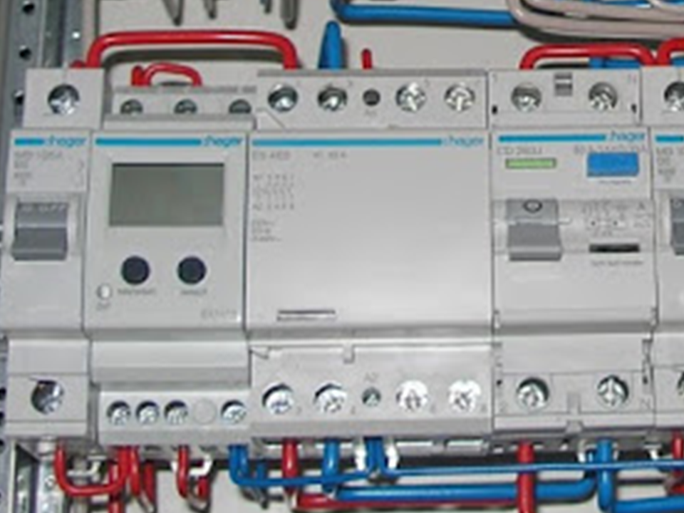

The load relay is best installed after the D.D.E in order to secure it for any leakage or any short circuit, although I have seen it put in and before the DDE as in the above photos.
Where placed
The monitor is installed after the main switch and main fuse and before any other hardware in the panel so that it can monitor the voltage.
At this point we would like to remind you that the correct order of placement of the general elements technically and legally according to ELOT HD 384 in the electrical panel of the installation is:
We start with the PPC supply to the house connected in series
General switch
General Safety
Fuse disconnector with fuse 1A or automatic fuse 1A
Voltage
-phase indicator with blue and green light
Leakage Relay (D.D.E)
Load relay (The load relay must have contacts that can withstand the MAX current (A) that can pass through the panel ! eg for 35A fuse = 10mm^2 NYA supply wires we would put a 40A load relay) .
The load relay is installed after the D.D.E (although I have seen it before as in the following photos) so that it is also secured against any leakage or short circuit.
To secure the monitor we must use a 1A automatic or fuse.

Scheme of voltage monitor with the load relay after the DDE
Voltage monitor design with load relay before DDE

When we also have lightning arresters, the order is:
General Switch Lightning Arrester
Fuses Lightning
Arrester Voltage
monitor Power relay that the monitor commands and at the output of the relay we put general fuses and DDE
(This order is according to Hager)
An arrangement that I have come across many times is the one below

At this point, we should emphasize that the voltage monitors provide us with another functionality and the lightning arresters another, I am referring to this issue because there is confusion between these two.
Our voltage monitor protects against permanent overvoltage or undervoltage.
While lightning arresters are devices that protect us from shock voltages and currents. which the supervisor cannot undertake and where he himself is exposed.
So for a more effective protection device we should install a lightning arrester in the electrical panel of our house.
Also, the voltage monitor isolates our installation in case of a voltage error and cannot ensure its stabilization. This function is provided by a voltage stabilizer.
Some examples of trend monitors


Single-phase product presentation
The EU 102 single-phase monitor allows the monitoring of direct or alternating voltage connected to terminals 5 and 9.
The EU 102 is programmable.
The following parameters can be defined:
● mode of operation (monitoring of overvoltages, undervoltages or both)
● the type of signal (dc or ac),
● voltage limits and hysteresis,
● the reaction time t1,
● the memory function.
The EU 102 has an LCD display screen, two setting buttons and a function indicator
Technical characteristics
Electrical characteristics
● Power supply: 230 V 50/60 Hz
● Consumption P ≤ 3 VA
Functional characteristics
● voltage limits :
15 V to 700 V DC
15 V to 480 V AC
● Hysteresis :
5 to 50 % of the corresponding limit you set
● Reaction time (t1)
0.1 to 12 s
Ambient conditions
● Operating temperature : -20 to +55 °C
● Storage temperature: -40 to +70 °C
Connection
conductors ● multi-strand up to 4 mm2
● single-strand up to 6 mm2 Normal
mode
In normal mode the screen shows the measured voltage.
If an error occurs and the memory is active, then you must press reset to return the product to normal operation.
The indicator represents the errors:
it flashes during the reaction time t1 (see Programming) and after this it remains
on Programming
By pressing the set and select keys simultaneously for 3 sec you enter the
programming mode. The display shows Prog for 1 sec.
set key: to validate a choice
select key : to cycle through parameters or their values.
The programming steps are as follows:
➀ Selection of signal type: AC or DC
➁ Selection of supervision type:
overvoltage (Up)
undervoltage (Lo)
overvoltage and undervoltage (Up Lo)
➂ Selection of voltage limits:
If you have selected Up supervision then you must set the upper limit
If you have selected Lo monitoring then you must set the lower limit
If you have selected Up Lo monitoring then you must set both limits
➃ Determination of hysteresis Hys (Volt).
If e.g. you have set the upper limit to 250 V and an overvoltage occurs, then for the supervisor to reactivate your circuit, the voltage must drop below 250 - Hys V. If you set, say, Hys=20 V, then the circuit your will only be activated again if the voltage drops below 250 - 20 = 230 V.
If you have selected Up Lo monitoring then you do not need to set hysteresis.
➄ Determination of the reaction time t1 (in sec).
In the event that the monitored voltage exceeds the limits you have set, then the monitor will interrupt the circuit it controls in time t1. If the over-/undervoltage lasts less than t1 then the supervisor will not react
➅ Memory mode selection :
memory active : yes M
in this case the supervisor does not automatically reset the monitored circuit. You should press reset to reset
memory inactive : no M
in this case the monitor always automatically resets the monitored circuit.
➆ End of programming.
To validate the entire programming press set. If you press select then you return to steps 1 to 6
Three-phase voltage monitor Hager EU302
Here I would like to show the Hager EU302 voltage monitor. The reason I focus on this particular one is because it contains difficult to understand blueprints. (from http://fubar.gr )
For this reason, I will try to decipher the user manual, so that it is easier to understand for anyone who wants to install the same monitor model.
The user manual can be downloaded here: Hager EU302
So let's start the decryption. The first diagram is quite self-explanatory:

It shows how it is connected to the three phases (parallel to the phase lines, at terminals 1, 5 and 9 respectively) and the minimum and maximum cross-sections of the conductors, depending on whether multi-core or single-core cable is used. Terminals 2,4 and 6 are relay contacts, with 6 being the common, 4 being Normally Closed and 2 being Normally Open.

It also has an on-off switch, without any description on it, and two sliders, one for the time (ranging from 0.1 to 12 seconds) and one for the level in percent, from 5% to 20%. One would have expected them to have written a little more detailed description on the faceplate as to exactly what this percentage and time mean so that the electrician could understand at a glance without having to refer to the owner's manual. And as we'll see next, it's not so obvious what exactly these sliders do.
To the left of the diagram above, is the table below, which has no title or description.

These, as I understand it, are the so-called Absolute Maximum Ratings, i.e. the values of voltage, current, temperature, etc. which must not be exceeded under any circumstances and for any period of time, otherwise permanent damage to the device may occur.
The confusing thing is Ik. At first I thought it was some kind of current, but it doesn't have any intensity unit after the number 3. So I think it means the IK rating, or impact protection rating, which roughly represents the resistance of the device to shocks. Whether a letter is uppercase or lowercase is very important in technical manuals because it can mean something completely different.
On the bottom half of the page we see the diagram below, which fully describes the operation of the watchdog, in the most difficult way possible!

Let's look at the upper part first:

This at first glance appears to be a very irregular sinusoidal voltage waveform. But it is not the sine of the "real" alternating voltage, but its RMS value, and we understand this from the vertical axis, which starts at zero.
If it were a representation of the sine of the voltage, then it should also take negative values and be symmetrical about the horizontal axis.
In other words, this chart shows a trend that is breaking out. On the left it shows voltage dips, while on the right it shows surges. If the voltage was normal and absolutely stable, then it would be represented by the red line in the diagram below as Un, i.e. nominal voltage. In the user manual of the similar model Hager EU301the corresponding diagram shows the nominal voltage Un more correctly

The chart has four different trend levels marked. Let's take the right part with the surges first. The upper voltage is noted as Up=1.15 Un. The voltage Un is the nominal voltage and is defined based on the document CENELEC HD 472 S1 throughout the European Union as 230 Volt RMS +-10%. That is, the normal variation can be from 207 to 253 Volts RMS.
So the Up voltage on the schematic is defined as 1.15 Un or 15% above nominal, or 264.5 Volts RMS, assuming the Un voltage is exactly 230 Volts.
Immediately below the Up trend, we have the Up – 1%Up trend. If we calculate this, it comes out to 261.85 Volts RMS.
Now let's go to the left part of the diagram that deals with sub-voltages. The lowest noted voltage is Lo=Un-Δu.
What is ă is stated below:

Therefore Δu is adjusted by the regulator with the inscription level(%) and is the percentage of the nominal voltage Un.
Suppose we choose the minimum percentage, i.e. 5%. Then Δu = 5% Un = 11.5 Volts RMS.
Therefore the voltage Lo becomes: Lo=230-11.5 = 218.5 Volts RMS
Therefore the voltage immediately above Lo+1%Lo equals 220.69 Volts RMS
Now let's see what these levels mean voltage and how the monitor reacts accordingly.
In the plot I have noted the trends we calculated earlier and numbered the interesting time points on the horizontal axis. I remind you that in the example we consider Un=230V and Level=5%, otherwise, these voltages will come out different.

This diagram shows us when the relay contact is activated and deactivated (which we usually use to arm another power relay - relay), and when the Def light is on, while the Memo switch is OFF.
So we see that starting from time point zero the voltage starts and increases gradually until it peaks at the voltage Un. At this stage the monitor does not detect any fault, so I assume that at startup it has a small "grace period" until the voltages stabilize.
Then, from the Un value, the voltage starts to fall. It drops below 220.69V but nothing happens, except when at time point 1 the voltage drops below 218.5V. From then on, we see that the Def light flashes for a period of time t (which we set with the slider on the front of the device) and when this period of time passes, the relay contact is activated (and therefore with the standard connection method it will the installation is interrupted).
The voltage then gradually recovers, rising above the 218.5 Volt point, but nothing is done until the voltage rises above 220.69 Volts at time point 2, at which point the relay contact is also de-energized (and consequently the power supply to the facility is restored).
So here we see that there are two voltage levels. Supply is interrupted when the voltage drops below the low level of 218.5 Volts, but resumes when it rises above the high level of 220.69 Volts.
This is called hysteresis and we also use it in electronics, when for example we make a voltage comparator (comparator) with an op-amp. If we had only one voltage level, then the slightest micro-changes in voltage near that level would cause the watchdog to open and close its contact very quickly and consequently cut and restore the supply rapidly, which would more damage to the installation. Hysteresis gives more stability to the system. This function is also called Schmitt Trigger.
And the exact same function exists in the case of overvoltages. That is, the supply is interrupted only when the high point of 264.5 Volts is exceeded, and it resumes when it falls below the low point of 261.85 Volts.
The other characteristic we observe from the diagram is that if the overvoltage-undervoltage lasts for a period shorter than the one we have chosen, then the supply is not interrupted (time points 3-4 and 9-10).
If again the voltage goes completely to zero, i.e. phase loss (time point 6) then the monitor turns off and stops working.
Here's an important note! The watchdog relay contacts don't actually work as the schematic shows!
The schematic implies that normally the relay coil is de-energized and pin 6 is connected to pin 4, and when overvoltage or undervoltage is detected, then the relay is activated and pin 6 is connected to pin 2.
But in reality when the monitor detects normal voltages, then it activates its relay and contact 6 is connected to contact 2. When it detects overvoltage or undervoltage then the relay is deactivated and contact 6 is connected to contact 4.
Consequently, the supply of the relay must be between the contacts 6 and 2, and not 6 and 4.
Its operation could not be otherwise, because if it was done as in the diagram, then in case of loss of one phase, it would continue to provide the installation with the other two, essentially canceling one of the main reasons we put a supervisor in an installation!!!
Regarding the Memo switch, when it is on it means that the supply will not automatically come back after overvoltage-undervoltage, but we will have to lower and re-raise the switch manually for it to come back.
So to summarize:
In this particular Hager EU302 voltage monitor model:
We can adjust the undervoltage level, from 5% to 20% below the rated voltage
The overvoltage level is fixed at 15% above the rated voltage
We can set the time interval between overvoltage-undervoltage detection and supply interruption from 0.1 to 12 seconds.
If the overvoltage-undervoltage lasts less than the predetermined time then the supply is not interrupted.
The supply is restored immediately when the voltage returns 1% above the lower undervoltage point or 1% below the upper overvoltage point. There is no reset delay option like other monitors have.
If the Memo switch is ON then even if the voltages return to normal, the supply will remain off.
It does not appear from anywhere that the specific monitor can detect phase asymmetries or phase succession. Therefore, if we want asymmetry and sequence control in the installation, then we should choose another monitor model, or combine it with an asymmetry and sequence monitor, such as the Hager EU300.
It is not specified if Un considers 230 Volts as a constant voltage or if there is a "learning" period during which it adapts to the local voltage of the installation. My personal opinion is that the latter happens, as otherwise there would be other models of overvoltage-undervoltage monitors in the Hager range, but this is the only one.
Therefore, the conclusion is that the specific monitor is suitable for three-phase installations in which the loads are single-phase, i.e. there are no three-phase motors or transformers, where in such a case we want the monitor to check both for asymmetry and for phase sequence.
To thank the ELECTRICAL SCIENTISTS of the 1st EPAS OAED THESSALONIKI for the amazing technological content and the wonderful articles they publish on their blog.