


What is the error loop
In many cases such as in densely populated areas in practice it is difficult or impossible to measure earth resistance with auxiliary electrodes because the necessary space cannot be found to place the auxiliary electrodes. So we resort to measuring the resistance of the phase fault-protection conductor loop. Fault loop is the path through which, due to a fault, current flows to the earth and which starts and ends at the point of the fault. The purpose of this measurement is to measure the impedance of the loop that will be created if, in a TN or TT earth connection system, it occurs fault of negligible impedance between active conductors, or between a phase conductor and an exposed conductive part or a protective conductor.
The fault loop formed when the phase conductor, due to faulty or worn insulation, comes into contact with the exposed conductive parts of a device is shown in the figure below.

If a phase conductor comes into contact with the earth conductor in an installation or in a device, the short-circuit current that will be created can be large enough to cause an electric shock or become the cause of the creation of a fire. Under normal conditions the corresponding circuit fuse or other protective device will activate within tenths of a second cutting off the supply. But this will happen on the assumption that the loop resistance of the circuit is low enough so that the corresponding short-circuit current generated is sufficient to activate the circuit protection.
In the opposite case, i.e. if in an electrical installation the loop resistance is high and the short-circuit current is relatively small, then the protective device will activate slowly or will not activate at all, with the consequence that the user is at risk of electric shock or the conditions for the fire event.
What the error loop resistance measurement shows us
The fault loop resistance does not depend on the earth resistance in neutral networks (TN). So measuring the fault loop resistance does not tell us if the ground resistance is correct. It shows us whether the protective devices we use (overcurrent and short-circuit fuses and leakage relays ) will act in the prescribed time so that the life of the user of the installation is not threatened or there is no risk of fire.
Control of automatic power cut-off in TN systems To apply the protection method with <<automatic cut-off of power supply>> in the case of a TN neutral earthing system , it is necessary to select an appropriate protection device, to protect against overvoltages, which in the event of a fault will automatically cut off the power supply within a predetermined time. The satisfactory fault response of the protection device to be chosen depends, in addition to the nominal characteristics of the device, on the quality of the loop in which the fault current will circulate.
A) Regarding the rated characteristics of the protection device, the rated current of the device and the characteristic time-current functions are of critical importance for the implementation of the protection with <<automatic interruption of the supply>>.
In other words, an important role for the implementation of the method is whether, for example, we have chosen a fused or automatic fuse to secure the circuit and even if the micro -automatic has a B or C operating characteristic , etc.
B) The quality of the fault loop through which the fault current will flow is controlled by the impedance value Zs that the loop exhibits.
It should therefore be verified:
a) The suitability of the protection device chosen for the automatic interruption of the supply
b) The suitability of the fault loop by measuring the resistance Zs it displays.
The aim of measuring the impedance of the fault loop in the case of a TN supply system is to establish that within the loop, in the event of a fault, a current capable of causing the disconnection of the protection device will be able to circulate within the time provided by the standard, so that do not develop a dangerous contact voltage. The prescribed time is 0.4 sec for 230V power supply lines for portable or mobile devices and 5 sec for distribution circuits (see table below).

Therefore, the maximum acceptable value for Zs to be measured during the fault loop control process should satisfy the relationship: Zs <=230V/Ia where:
Zs: resistance of the fault loop which includes the source, the active conductor up to the point of the fault and the protective conductor between the fault and the source.
Ia: the current that causes the automatic disconnection of the protection device in the time provided for each case. E.g. for MCB 10A the Ia is Ia=5Ion=5*10A=50A If a differential current protection device (DPE) is used, then Ia is the rated operating differential current of the device
Acceptable error loop impedance measurement results
The value of the measured fault loop resistance Zs depends in each case on the protection device used in the power line under control. Indicative values for the maximum value of Zs are given in the tables below, for the various types of protection devices and for tripping times of 0.4s and 5s.


Also, knowing the maximum value of the fault loop impedance Zsmax , the minimum required fault current Ikmin can be calculated , which will activate the protection device and cause the circuit to be cut off. The calculation of Iκmin is made from the relationship: Iκmin=230V/ ζsmax
The following table gives both the values of the fault loop impedance and the minimum required value of the fault current Iκmin for the cases of power supply circuits of common household single-phase electrical appliances.
To determine the values in the table below, it has been assumed that the protection device selected is microautomatic type B, as well as the required disconnection time of the microautomatic is 0.4s for a supply voltage of 230V.
Note: In any case, in order for the protection to work with <<automatic cut-off>>, the value of the intensity of the expected fault current Ik must be greater than the current required to activate the protection device selected Ikmin .
When measuring with the certified instrument we will measure:
the fault loop resistance Zs (it should be < than the fuse Zs ).
and the expected short-circuit current Ik that the loop will flow when a fault occurs (it should be > than the Ik that the fuse will cut). The Zs and Ik of the fuses are taken from tables as we saw above.
and the expected short-circuit current Ik that the loop will flow when a fault occurs (it should be > than the Ik that the fuse will cut). The Zs and Ik of the fuses are taken from tables as we saw above.
Comment: The error loop is examined for the control protocol on each line of the circuit. In the case of a TT earthing system , the measurement of the fault loop impedance is accepted as the value of the earthing resistance, knowing that it gives a value greater than the actual value of the earthing resistance due to the fact that conductors participate in the whole arrangement (ΕΛΟΤ HD384 paragraph 612.6.2, note 2 ).
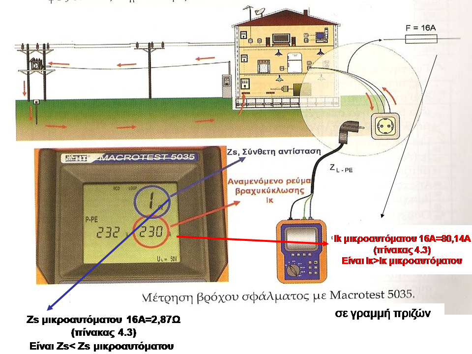
Example: A line of power outlets is secured with a 16 A type B micro-circuit breaker in an installation with a TN earthing system. For this case the predicted disconnection time is 0.4s.
Based on the operating characteristics of the specific micro -automatic, to activate within a time of 0.4s , an error current of at least five times the nominal (5*16=80 A) is required.
So for this particular supply line the maximum acceptable value of the fault loop impedance should be ζs=230/80=2.875Ω and correspondingly the minimum expected fault current will be Ik=80A.


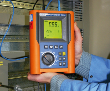
In the following measurement example with the MACROTEST 5035 instrument, in a socket line protected by a 16A automatic fuse, the measured Zs should be less than or equal to 2.87Ω and the current that must circulate in the loop Ikmin to break the fuse to 0, 4sec to be greater than or equal to 80.14A according to the above tables. We see that the measurements are acceptable.
In the following example of two measurements with a Eurotest instrument we have a correct and an incorrect indication:
In a line secured with a 16A type C automatic fuse, the measured Zs should be less than or equal to 1.44Ω and the current that must circulate in the Ikmin loop to break the fuse in 0.4sec should be greater than or equal to 80, 1A according to the tables above. We see that the measurements are acceptable.
In a line secured with a 10A type B automatic fuse, the measured Zs should be less than or equal to 4.6Ω and the current that must circulate in the Ikmin loop to break the fuse in 0.4sec should be greater than or equal to 50A according with the above tables. We see that the measurements are not acceptable.

For the most correct documentation of the fault loop information, the measurements of the complex value of the fault loop resistance Z s as well as the expected short-circuit current Ik or Isc have the same weight in relation to the evaluation of results. It would make sense to double-list the results. For many the value of the expected short-circuit current is more important, due to the fact that we confirm the correct use or selection of the characteristic curve of the micro- automatic (B, C, D etc) in relation to its minimum short-circuit current I sclimit .
The closer the PPC transformer is to the building, the greater the value of the expected short-circuit current Ik or I sc
The closer the PPC transformer is to the building, the greater the value of the expected short-circuit current Ik or I sc
Important Note: Using a test current of less than 15mA can in some special cases lead to misleading measurements or measurements with a very large value error for the fault loop impedance. In order to obtain an indicative reference value of the resistance ΖS, it is advisable to precede a measurement of the fault loop impedance at the input of the supply to the installation and before the intervention of the residual current protection device, as shown in the figure below. In this way a test current greater than 15mA can be used on the one hand and a safe one is obtained on the other hand
conclusion on the value of the impedance of the fault loop ΖS displayed by the central supply line of the electrical installation.
Then we can for the individual power supply circuits of the consumptions of the electrical installation which are protected by D.D.P. to use the test current of 15mA, since having obtained from the previous measurement a measure of comparison, we are able to discard measured values with a large deviation which are due to possible errors of the method.


The fault loop in TT earthing systems
In the TT earthing system (direct earthing) in the event of a fault in the insulation between a phase and the protective conductor or an exposed conductive part, the fault loop in addition to the conductors (active conductors and protective conductor) also includes a path part in the ground.
So the fault loop in this case will only be created if there are earths from both sides or that these earths are connected (the connection is made through the conductive path of the ground where they are placed).
Because earthing resistances intervene the fault current between phase and exposed conductive parts is less than the current of a solid short circuit (as in the TN earthing system), but can be of such a value that dangerous contact voltages can occur (as e.g. when grounding is done by connecting to an extensive metallic water supply network).

The fault loop resistance should be checked to see that the requirement is met _ _ automatic cut -off so that the contact voltage will not exceed 50V and will cut off in 5sec Surge protection devices are not suitable for protection against indirect contact in the TT earthing system unless the resistance of the earthing electrode is very low.

Examples of completing a protocol formIndicative orders of magnitude for earth resistance and for different RCD nominal values are summarized in the table below:


Fault loop measurement in TN- CS grounding systems ( points to pay attention to)
If there are electrical consumptions in operation in the circuit to be measured, they can affect the result of the measurement.
If there are leakage currents or extraneous voltages in the protective conductor they can also affect the measurement result.
If there is backup power in the installation ( eg generator) the fault loop measurements must be repeated with the backup power in operation.
Fault loop measurement in TN- CS grounding systems ( unacceptable results) If the results of a measurement do not meet the standard (large values) it should be investigated first whether it is a measurement error, a problem with the supply ( e.g. PPC) or installation error.
In order to identify whether it is a fault of the supply ( eg PPC) or a fault of the installation, measurements should be made very close to the point of supply.
If it is found that the prices remain high there as well, then it is a supply error and the relevant institution must be informed about its restoration.
A measurement error can be caused by:
Poor loose connections
Small pipe cross-sections
Defective electrical materials
After the cause of the deviation has been identified and corrected, we repeat the measurement


Phase-to-neutral or phase-to-phase fault loop
measurements These measurements are not required by the standard or by Legislation. But they are useful in practice.
In a TN- CS earthing system, by comparing the fault loop measurements between phase-neutral and between phase-protection conductor, the quality of the neutralization can be evaluated .


An example in practice: In a house in Crete (TN- CS system ) the fault loop measurement in the panel between phase and protection conductor gives 24.5Ω.
At the same point the phase-neutral fault loop measurement gives 1.1Ω.
In another neighboring house supplied by the same substation the fault loop measurement in the panel between phase and protective conductor gives 1.3Ω.
At the same point the phase-neutral fault loop measurement gives 1.2Ω. Conclusion: The neutralization in the first apartment building is problematic. If there was no differential current arrangement the installation would be dangerous. Because the
neutralization (PEN-PE connection) is done at the meter, the competent operator of the distribution network should be requested and intervened there ( e.g. PPC) Notes: In initial checks where the installation has not been initially supplied, but also in re-checks when supply has been interrupted, fault loop measurements are not possible.
In these cases it is suggested that these measurements be made after the installation is powered and the results documented in a supplementary protocol.
If the facility has an alternative backup power supply ( e.g. generator) the above measurements should be repeated with it and the results documented in the control protocol.
source: Most of the information is from Saleuris-Hatzisofianou (New YDE and control protocols for Electrical Installations)
Blog News : Join the team electricians911 ask and answer questions upload articles and videos Here