


Three-phase motor start star connection / triangle
Εκκίνηση τριφασικού κινητήραGiannis Alifragkis automation, Industrial automation,


Materials:
1: a power relay with an auxiliary contact : no
2: a power relay with an auxiliary contact : nc
3: a power relay with three auxiliary contacts: two: nc and a no
4: a thermal one with an auxiliary contact : nc
5: one time
6: two Buttons with reset one: nc and the other no
7: an induction motor 380/660
NOTE:
The Control circuit depending on the operating conditions can be supplied by two phases - from phase and neutral and voltage from transformer .
The control circuit is powered by a transformer with a voltage of 42 to 110 volts maximum when the conductors where it is composed have an area on tanks with flammable materials and when part of it comes in contact with humans.
Plan:

EXPLANATION:
By pressing the Start Button, the KM1 coil will be supplied with voltage, as a result of which its contacts will be closed. with the KM1 will be put into operation and the coil of the timer so the voltage passes through contacts 7 and 5 of the timer in NC 21-22 of KM3 resulting in arming the coil of KM2 by arming the KM2 the motor now operates in star connection with limited starting intensity while its auxiliary contact 11-12 from NC became NO
the timer will remain on contacts 7 and 5 for as long as we have set this time is necessary for the engine to develop a certain number of revolutions and to reduce the starting intensity due to the progressive countercurrent force. then the chronicle makes the switch from contact 5 to contact 6 then KM2 will be disarmed and its contacts from NO will become NC again resulting in the arming of KM3. After KM3 has armed its auxiliary contacts change status and so the contact 11-12 from NC becomes N
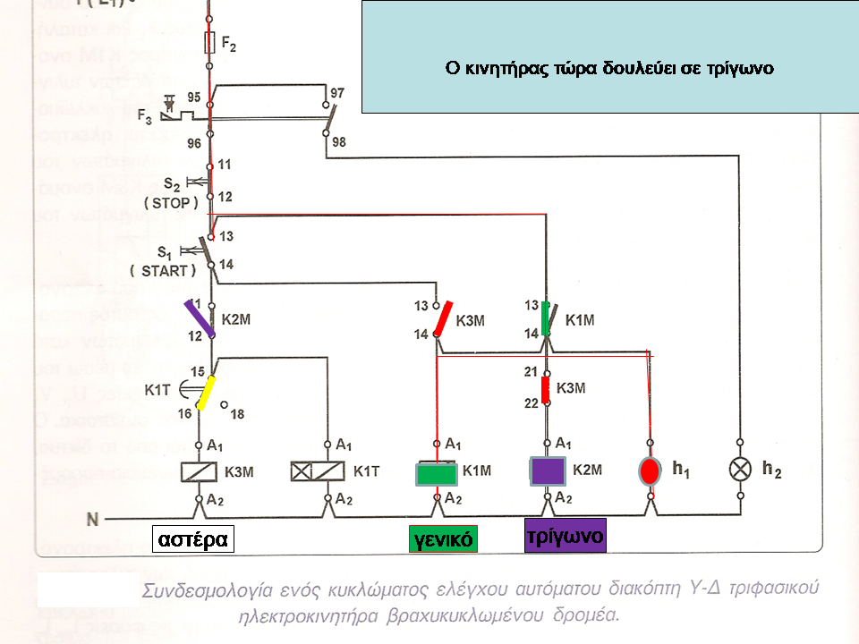
By cutting off the phase T to the time the 21 - 22 from NC become NO resulting in the de-excitation of the time coil and the contact 13 - 14 from NO become NC thus holding the KM3 means of the NC contact 11 -12 of KM2 with it the way our engine now works in a triangle connection.
As for the contacts 95-96 of the thermal and 11-12 of the Button (stop) are connected in series so that when the thermal needs to stop the operation or for any other reason we need to stop ourselves from the Button stop.
In the drawing it is seen that you connect the thermal to the output of KM1 this has as a result that the current that passes through the thermal to the normal operation passes through the coils of the motor. the current in the motor coil is less than the line current so current passes through the thermal that reaches 58% of the actual operating intensity for this in the triangle star switches the thermal is set to 58%.
In more detail
ASTER-TRIGON AUTOMATIC SWITCHThe engine starts at a star and then just before reaching its nominal speed it turns into a triangle.
Inside the three-phase motors there are 3 composite coils (windings) which are U1-U2, V1-V2, W1-W2 or VX, VY, WZ


Asynchronous short-circuit rotor motors are simple to build and have low maintenance costs. For this reason their use is widespread.
Their starting current is 4 to 8 times higher than the normal operating current. For this reason, starting the motor directly in a triangle connection, which is their operating connection, creates problems in the network (voltage drop).
To limit the starting current, but also to protect them, the star-delta (SW) circuit breaker is used, which is briefly referred to as the star delta.
Usually used in engines with more than three horsepower (about 2 KW).

At the start of the engine the three windings must be connected to a star wiring. For this purpose the ends U2, V2 and W2 are connected together, while the ends U1, V1 and W1 are connected to the phases L1, L2 and L3 respectively.
After the motor has been running for a period of time to reach approximately its rated speed, the circuit breaker changes the motor wiring from star to delta. This is done by bridging the ends U1-W2, V1-U2 and W1-V2 and connecting them in phases L1, L2, L3 respectively.
The starting current of an engine in star wiring is 3 times smaller than the starting current in triangle wiring.

Comparison of the two star and triangle connections
Suppose I connect two identical motors to the same network (next figure). Left in a star and right in a triangle

In the triangle connection we observe that while we apply to the motor polar voltage 400V, its coils are also supplied with 400V.
1. If the motor coils are made for 230V, in star connection the motor will run normally but in triangle connection they will be damaged immediately due to higher voltage.
2. If the motor coils are made for 400V, in the triangle connection the motor will operate normally, but in the star connection the following will happen:
a) The coils will receive a lower voltage than their normal
b) The motor power will be smaller
c) It will not be able to meet its load
d) It will operate at lower speeds and the current in the coils will be higher than the nominal
The result will be that the motor windings will burn after a while.
No load on the shaft the motor will run normally without problems
In the star connection the motor current is three times less than in the triangle connection, as shown below:


CONNECTIONS AND EXPLANATION
In the figure below the relay K1M is called the mains relay and connects the phases L1, L2 and L3 to the terminals U1, V1 and W1 of the motor respectively.
The K2M relay is called a triangle relay because, when activated, it connects the windings to a triangle connection (bridging the ends U1-W2, V1-U2 and W1-V2 in pairs).
Finally, the relay K3M is called a star relay because by activating it, it bridges the ends U2, V2 and W2 of the windings, connecting them in a star connection.
The K2M and K3M relays should never be activated at the same time, as this will cause a three-phase short circuit at positions 1,3,5 of the K3M relay.

To start the engine, switch the Q1 switch manually and then press the START button. Then an electric current passes through the coils of the relay K3M and the time K1T activating them.
Let us now consider what happens to the activation of the K3M relay. Closes the
normally open contacts of power 1-2, 3-4, 5-6 of K3M
· closes the normally open contact of 13-14
; opens the normally closed contact of 21-22
Closing contacts 1-2, 3-4 and 5-6 of the K3M, connects the motor windings to a star connection. The closing of the contact 13-14 has as a consequence the activation of the relay K1M, which through the contacts 1-2, 3-4 and 5-6 connects its power, through the thermal, the three phases L1, L2, L3 of the network with the terminals U1, V1, W1 of the motor windings. So the engine starts in star wiring. The opening of the contact 21-22 of K3M, excludes the activation of the relay K2M in parallel with K3M, which would have as a consequence the short circuit of the three phases.
By activating the relay K1M:
· closes the normally open contact of 13-14 by supplying power to the automation control circuit and after releasing the START start button. This is the contact of self-control
· The engine H1 indicator light illuminates.
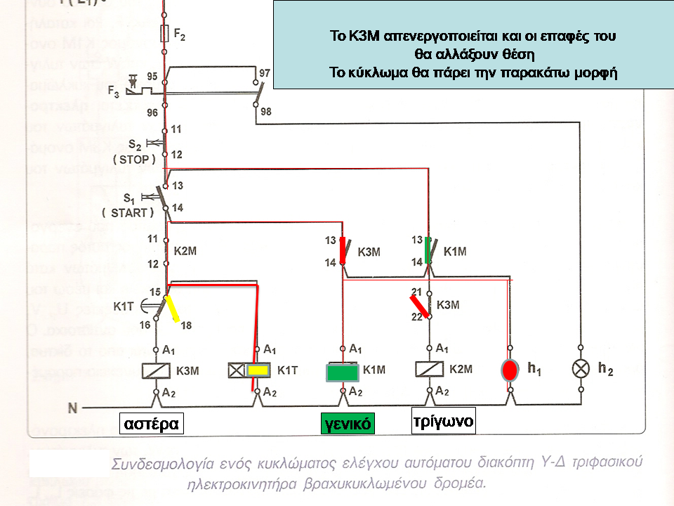
As mentioned by pressing START, the time K1T was also activated. When the time for which it has been set has elapsed, the contact of 15-16 opens. The K3M star relay is then deactivated, closing 21-22 by activating the K2M triangle relay, which connects the motor windings to a triangle connection.
The activation of K2M, opens the contact of 11-12, thus excluding the simultaneous activation of the relay star K3M.
Finally, pressing the STOP button cuts off the power to the entire control circuit, deactivating all relays and shutting down the motor. Then the H1 indicator light goes out.
The mission of the heat is to protect the engine from constant overload, which can damage its windings. So if the engine overload time exceeds the time during which the thermal F3 is set, then it is activated: Contact 95-96 opens, while 97-98 closes. Opening contact 95-96 has the effect of interrupting the supply of the relay coils and stopping the motor. Operating indicator H1 goes out while the fault lamp H2 lights up. At this point we report that the thermal current is set to 0.58.Ion (i.e. in the phase current of the triangle), where Ion is the rated operating current of the motor.
After eliminating the cause that caused the engine to overload, in order for the engine to restart, we press the thermal reset button.


 Let's look step by step again at the operation of the circuit


 In small motors instead of load switch, fuses and thermal I can use a magnetothermal, as in the following circuit

 Let's look at an alternative automation circuit with a time of 2 auxiliary contacts (17-18 immediate activation and 27-28 time delay)


Selection of relays depending on the motor power


Which motors can be connected to a star triangle switch
To connect a three-phase motor to the mains, the polar mains voltage must coincide with one of the operating voltages of the motor, which are indicated on its label. The possibilities of internet connection are given in the table below (the trend that can not be used is written in small letters)


Starting current
Large starting currents occur when starting three-phase motors. These currents cause a momentary voltage drop in the networks that supply the motors and which cause abnormalities in the proper operation of devices that want a constant operating voltage.
These voltage drops do not only depend on the Iek starting current, but also on the capacity of the power supply network.
For three phase motors in practice applicable with fairly good approximation the following values:
single phase motor (direct start) IEK = 6Ion
AC motor (direct start) IEK = 6Ion
AC motor (starting with Y / D) IEK = 2Ion
Daktylioforos engine Iek = 1.25Ion
In general, in Α.Τ.Κ.β.δ. their starting current or their peak current (Iek) is a multiple of their rated current (IN) depending on the characterization of the motor in terms of the number of its poles and we consider that it follows the data in the following table:
 The exact calculation of the starting current or peak current (IA) of Α.Τ.Κ.β.δ., results from their starting factor (k) - which is given to their technical characteristics by their manufacturer - on the nominal their current (IN), ie: Iek = k. IN
The limits of the maximum demand of the starting current set by the PPC in relation to the number of starts of the motor refer to the type of low voltage network (XT) that supplies the installation, that is, whether it is aerial or underground.
These limits are given in the table below:

In case the consumer has his own substation, then the limit of the allowed starting current set by PPC, depends on the apparent power (KVA) of the private substation.
These limits are given in the table below:

If none of the above is observed, we must limit the starting current in one of the ways to be the automatic switch of the bedroom.
If done earlier, the melting fuses may burn (because the motor has not reached its normal speed and the current will increase sharply to a large value during the early switch to a triangle) and after partial starts the triangle relay contacts are destroyed.
If it is done late, we have a reduction in the power and torque of the engine, which can also cause problems.
Switching time can be calculated empirically from engine noise as it accelerates.
However, it can be calculated more accurately by measuring the motor current.
The switch must be made when the starting current, as it decreases, falls to twice the rated motor current. This current can be measured with an ammeter and thus find the switching time.


When switching from star to triangle it arms the triangle relay and disarms the star relay at the same time. This causes strain on the motor and relays because it creates an instantaneous short circuit and spark when switching from star to triangle. In large motors I prefer to disarm the star relay first and after some msec arm the triangle relay.


Adjustable activation delay of 1-20 sec.
Delay of 40-60 msec in the activation of the triangle.
LED for triangle operation indicator.
It operates constantly under voltage.
See 30 KW (40.7HP) engine start with a star-delta switch. The change from star to triangle is done in about 40 seconds as you can understand from the change in engine noise in the following video
TEMPERATURE ADJUSTMENT
The thermal is set to 0.58 of the rated motor current
But let's see below why
Let the rated current of a 3F 400D motor is 10A.
If the engine started directly at D it would pull 6 * 10 = 60A
When the engine starts at a star Y the thermal will leak from 60/3 = 20A (IY = ID / 3) for a few seconds until it reaches the nominal speed.
When the motor turns in triangle D the thermal will leak from
10/2 = 5 A. For this reason I adjust the thermal to 0.58 * 10 = 5.8A
PROBLEM
We have a motor 10KW and co = 0.8
Find:
1 .Adjusting the engine heat if it starts directly
2.The engine start current if it starts directly
3.The engine heat setting if it starts with a power switch
4.The current that flows through the engine heat at the start time to a Y star, if it starts with a Y / D switch
5.The current that flows through the motor heat during the operation of the motor in a triangle D, if it starts with a power switch
SOLUTION
The motor current will be
I = P / (1.73 * V * co) = 10000 / (1,73 * 400 * 0,8) = 18 Α
Direct start
1. setting thermal to 18 Α
2. motor starting current Ιεκ = 6 * Ι = 6 * 18 = 108 Α
Starting with bed switch
3. setting thermal at 0.58 * I = 0.58 * 18 = 10.44 A
4. The current that flows through the motor thermal at the time of starting in star Y is Iek (Y) = Iek / 3 = 108/3 = 36 A
5. The current that flows through the motor heat during the operation of the motor in a triangle D is 0.5 * I = 0.5 * 18 = 9 A (I set the thermal to 10.44 A)
Manual star-triangle switch
In addition to the automatic star triangle switch, they used to use the manual one, where the transition from star to triangle is done manually, but it strains the engine because the switching time is at the operator's will.


three phase dol starter Control overload Indicator Power Wiring diagram
Books
https://elearning.teicm.gr/file.php/318/trifasikos_asynxronos_kinitiras.pdf
http://www.hlektrologia.weebly.com/uploads/6/7/1/5/6715419/p209_284.pdf
http: / /ebooks.edu.gr/modules/ebook/show.php/DSGL-C123/487/3182,12850/
http://okeanis.lib.puas.gr/xmlui/bitstream/handle/ele13033.pdf
http: // www.mie.uth.gr/ekp_yliko/kinitires.pdf
http://www.hlektrologia.weebly.com/uploads/6/7/1/5/6715419/p209_284.pdf
http: //www.mie.uth. gr / ekp_yliko / hlmhx_en6.pdf
Linking
https://www.matsakis.gr/syndesi_kinitirwn_astera_or_trigono_diafaneies.pdf
http://users.teilar.gr/~trogadas/MIXANES/ERGASTHRIO%20MIXANES%20AC/ergastirpsAC.pdf
. pdf
https://maredu.gunet.gr/modules/document/pdf
http://edume.myds.me/00_0070_e_library/10030/06_Electrical_installations_books/12/B15.pdf
https://maredu.gunet.gr/modules/ document / pdf
Works
http://artemis.cslab.ece.ntua.gr:8080/jspui/bitstream/123456789/13594/1/DT2017-0252.pdf
http://repository.library.teimes.gr/xmlui/bitstream/pdf
http : //eclass.sch.gr/modules/document/file.php/T522110/askisi_3_automati_ekkinisi_trif_kin_vrax_dromea.pdf
http://nefeli.lib.teicrete.gr/browse/sefe/VardakisMichalis2014.pdf
http://users.sch.gr //iliaslamprou/images/stories/askiseis_electrikwn_egkatastasewn/syndesi_kinitirwn_astera_or_trigono/project_seet_automatos_diakoptis_astera_trigwnou.pdf
http://repository.library.teimes.gr/xmlui/bitstream/
Other
https://hlektrologia.weebly.com/uploads/6/7/1/ 5/6715419 / p285_320.pdf
http://users.sch.gr/iliaslamprou/images/stories/askiseis_electrikwn_egkatastasewn/thema_6_monofasikoi_kinitires.pdf
https://elearning.teicm.gr/file.php/410/Single_phase_IM_SD.201./
. gr / xmlui / bitstream / handle / 123456789
http://okeanis.lib.teipir.gr/xmlui/bitstream/handle/123456789/2863/ele_40956.pdf
In the figure below the relay K1M is called the mains relay and connects the phases L1, L2 and L3 to the terminals U1, V1 and W1 of the motor respectively.
The K2M relay is called a triangle relay because, when activated, it connects the windings to a triangle connection (bridging the ends U1-W2, V1-U2 and W1-V2 in pairs).
Finally, the relay K3M is called a star relay because by activating it, it bridges the ends U2, V2 and W2 of the windings, connecting them in a star connection.
The K2M and K3M relays should never be activated at the same time, as this will cause a three-phase short circuit at positions 1,3,5 of the K3M relay.
To start the engine, switch the Q1 switch manually and then press the START button. Then an electric current passes through the coils of the relay K3M and the time K1T activating them.
Let us now consider what happens to the activation of the K3M relay. Closes the
normally open contacts of power 1-2, 3-4, 5-6 of K3M
· closes the normally open contact of 13-14
; opens the normally closed contact of 21-22
Closing contacts 1-2, 3-4 and 5-6 of the K3M, connects the motor windings to a star connection. The closing of the contact 13-14 has as a consequence the activation of the relay K1M, which through the contacts 1-2, 3-4 and 5-6 connects its power, through the thermal, the three phases L1, L2, L3 of the network with the terminals U1, V1, W1 of the motor windings. So the engine starts in star wiring. The opening of the contact 21-22 of K3M, excludes the activation of the relay K2M in parallel with K3M, which would have as a consequence the short circuit of the three phases.
By activating the relay K1M:
· closes the normally open contact of 13-14 by supplying power to the automation control circuit and after releasing the START start button. This is the contact of self-control
· The engine H1 indicator light illuminates.
As mentioned by pressing START, the time K1T was also activated. When the time for which it has been set has elapsed, the contact of 15-16 opens. The K3M star relay is then deactivated, closing 21-22 by activating the K2M triangle relay, which connects the motor windings to a triangle connection.
The activation of K2M, opens the contact of 11-12, thus excluding the simultaneous activation of the relay star K3M.
Finally, pressing the STOP button cuts off the power to the entire control circuit, deactivating all relays and shutting down the motor. Then the H1 indicator light goes out.
The mission of the heat is to protect the engine from constant overload, which can damage its windings. So if the engine overload time exceeds the time during which the thermal F3 is set, then it is activated: Contact 95-96 opens, while 97-98 closes. Opening contact 95-96 has the effect of interrupting the supply of the relay coils and stopping the motor. Operating indicator H1 goes out while the fault lamp H2 lights up. At this point we report that the thermal current is set to 0.58.Ion (i.e. in the phase current of the triangle), where Ion is the rated operating current of the motor.
After eliminating the cause that caused the engine to overload, in order for the engine to restart, we press the thermal reset button.


Selection of relays depending on the motor power


Which motors can be connected to a star triangle switch
To connect a three-phase motor to the mains, the polar mains voltage must coincide with one of the operating voltages of the motor, which are indicated on its label. The possibilities of internet connection are given in the table below (the trend that can not be used is written in small letters)


Starting current
Large starting currents occur when starting three-phase motors. These currents cause a momentary voltage drop in the networks that supply the motors and which cause abnormalities in the proper operation of devices that want a constant operating voltage.
These voltage drops do not only depend on the Iek starting current, but also on the capacity of the power supply network.
For three phase motors in practice applicable with fairly good approximation the following values:
single phase motor (direct start) IEK = 6Ion
AC motor (direct start) IEK = 6Ion
AC motor (starting with Y / D) IEK = 2Ion
Daktylioforos engine Iek = 1.25Ion
In general, in Α.Τ.Κ.β.δ. their starting current or their peak current (Iek) is a multiple of their rated current (IN) depending on the characterization of the motor in terms of the number of its poles and we consider that it follows the data in the following table:

The limits of the maximum demand of the starting current set by the PPC in relation to the number of starts of the motor refer to the type of low voltage network (XT) that supplies the installation, that is, whether it is aerial or underground.
These limits are given in the table below:

In case the consumer has his own substation, then the limit of the allowed starting current set by PPC, depends on the apparent power (KVA) of the private substation.
These limits are given in the table below:

If none of the above is observed, we must limit the starting current in one of the ways to be the automatic switch of the bedroom.
Adjusting the switching time of the windings
Adjusting the switching time of the windings requires special attention. As mentioned above, the switch must be made when the engine is approaching its operating speed.If done earlier, the melting fuses may burn (because the motor has not reached its normal speed and the current will increase sharply to a large value during the early switch to a triangle) and after partial starts the triangle relay contacts are destroyed.
If it is done late, we have a reduction in the power and torque of the engine, which can also cause problems.
Switching time can be calculated empirically from engine noise as it accelerates.
However, it can be calculated more accurately by measuring the motor current.
The switch must be made when the starting current, as it decreases, falls to twice the rated motor current. This current can be measured with an ammeter and thus find the switching time.


Let's look at some times with double adjustment time
In these times we set in addition to the time when the transition from star to triangle will take place and another set time in msec.When switching from star to triangle it arms the triangle relay and disarms the star relay at the same time. This causes strain on the motor and relays because it creates an instantaneous short circuit and spark when switching from star to triangle. In large motors I prefer to disarm the star relay first and after some msec arm the triangle relay.

Special timer for starting engines with a star triangle
There are some special timers to avoid the difficult wiring of the auxiliary circuit when we use a simple timer. Also its use increases the life of the relay contacts and in case of failure of the timer, the motor does not start at a star as with simple chronicles.
Adjustable activation delay of 1-20 sec.
Delay of 40-60 msec in the activation of the triangle.
LED for triangle operation indicator.
It operates constantly under voltage.
See 30 KW (40.7HP) engine start with a star-delta switch. The change from star to triangle is done in about 40 seconds as you can understand from the change in engine noise in the following video
TEMPERATURE ADJUSTMENT
The thermal is set to 0.58 of the rated motor current
But let's see below why
Let the rated current of a 3F 400D motor is 10A.
If the engine started directly at D it would pull 6 * 10 = 60A
When the engine starts at a star Y the thermal will leak from 60/3 = 20A (IY = ID / 3) for a few seconds until it reaches the nominal speed.
When the motor turns in triangle D the thermal will leak from
10/2 = 5 A. For this reason I adjust the thermal to 0.58 * 10 = 5.8A
PROBLEM
We have a motor 10KW and co = 0.8
Find:
1 .Adjusting the engine heat if it starts directly
2.The engine start current if it starts directly
3.The engine heat setting if it starts with a power switch
4.The current that flows through the engine heat at the start time to a Y star, if it starts with a Y / D switch
5.The current that flows through the motor heat during the operation of the motor in a triangle D, if it starts with a power switch
SOLUTION
The motor current will be
I = P / (1.73 * V * co) = 10000 / (1,73 * 400 * 0,8) = 18 Α
Direct start
1. setting thermal to 18 Α
2. motor starting current Ιεκ = 6 * Ι = 6 * 18 = 108 Α
Starting with bed switch
3. setting thermal at 0.58 * I = 0.58 * 18 = 10.44 A
4. The current that flows through the motor thermal at the time of starting in star Y is Iek (Y) = Iek / 3 = 108/3 = 36 A
5. The current that flows through the motor heat during the operation of the motor in a triangle D is 0.5 * I = 0.5 * 18 = 9 A (I set the thermal to 10.44 A)
Manual star-triangle switch
In addition to the automatic star triangle switch, they used to use the manual one, where the transition from star to triangle is done manually, but it strains the engine because the switching time is at the operator's will.


Books
https://elearning.teicm.gr/file.php/318/trifasikos_asynxronos_kinitiras.pdf
http://www.hlektrologia.weebly.com/uploads/6/7/1/5/6715419/p209_284.pdf
http: / /ebooks.edu.gr/modules/ebook/show.php/DSGL-C123/487/3182,12850/
http://okeanis.lib.puas.gr/xmlui/bitstream/handle/ele13033.pdf
http: // www.mie.uth.gr/ekp_yliko/kinitires.pdf
http://www.hlektrologia.weebly.com/uploads/6/7/1/5/6715419/p209_284.pdf
http: //www.mie.uth. gr / ekp_yliko / hlmhx_en6.pdf
Linking
https://www.matsakis.gr/syndesi_kinitirwn_astera_or_trigono_diafaneies.pdf
http://users.teilar.gr/~trogadas/MIXANES/ERGASTHRIO%20MIXANES%20AC/ergastirpsAC.pdf
https://maredu.gunet.gr/modules/document/pdf
http://edume.myds.me/00_0070_e_library/10030/06_Electrical_installations_books/12/B15.pdf
https://maredu.gunet.gr/modules/ document / pdf
Works
http://artemis.cslab.ece.ntua.gr:8080/jspui/bitstream/123456789/13594/1/DT2017-0252.pdf
http://repository.library.teimes.gr/xmlui/bitstream/pdf
http : //eclass.sch.gr/modules/document/file.php/T522110/askisi_3_automati_ekkinisi_trif_kin_vrax_dromea.pdf
http://nefeli.lib.teicrete.gr/browse/sefe/VardakisMichalis2014.pdf
http://users.sch.gr //iliaslamprou/images/stories/askiseis_electrikwn_egkatastasewn/syndesi_kinitirwn_astera_or_trigono/project_seet_automatos_diakoptis_astera_trigwnou.pdf
http://repository.library.teimes.gr/xmlui/bitstream/
Other
https://hlektrologia.weebly.com/uploads/6/7/1/ 5/6715419 / p285_320.pdf
http://users.sch.gr/iliaslamprou/images/stories/askiseis_electrikwn_egkatastasewn/thema_6_monofasikoi_kinitires.pdf
https://elearning.teicm.gr/file.php/410/Single_phase_IM_SD.201./
. gr / xmlui / bitstream / handle / 123456789
http://okeanis.lib.teipir.gr/xmlui/bitstream/handle/123456789/2863/ele_40956.pdf