


The start of Α.Τ.Κ.β.δ. with full mains voltage in its windings, ie directly, is usually carried out without the approval of PPC, and concerns low power motors with peak current (eg less than 30 A for overhead network and frequent starts more than one per hour) .
Κύκλωμα Απλής Εκκίνησης Α.Τ.Κ.Β.Δ Με Την Πλήρη Τάση Του Δικτύου
Essentially, in this case, the starts of Α.Τ.Κ.β.δ. do not create voltage dips in existing interoperable electrical circuits / installations.
We will try to present the "direct" start of Α.Τ.Κ.β.δ. with wired logic automation circuit function.
Power and automation circuit - Brief / descriptive explanation of operation
I put in position ON:
the fuse disconnector F1 of the power circuit of Α.Τ.Κ.β.δ. and
the F3 microcontroller of its automation circuit.
We observe that the indicator waiting light H2 operation lights up through the closed auxiliary contact K1 / 31-32 of the relay K1.
I press the start button S2, the coil of the relay K1 / A1-A2 is activated, so:
the 3 main contacts of the relay K1 are activated at the same time, the self-holding contact K1 / 13-14, the second open auxiliary contact K1 / 23-24, whereupon the operation indicator H1 turns on, while the indicator standby operation H2 turns off through the closed auxiliary contact K1 / 31-32 of the relay K1 that opens.
I press the stop button S1 and the coil of the relay K1 is deactivated, at which point the operation of the Α.Τ.Κ.β.δ. stops. which switches to its standby mode.
If during the normal operation of Α.Τ.Κ.β.δ. happen e.g. an overload in the windings of the ATCB, the bimetallic thermal F2 is activated, so:
the closed contact of the thermal F2 / 95-96 opens and the current in the coil of the relay K1 / Α1-Α2 is interrupted with the consequence that the operation of Α.Τ.Κ.β.δ. which switches to its standby mode, while at the same time
the open contact of the thermal F2 / 97-98 closes and the alarm of this H3 (siren) is activated.
After the repair of the damage, Α.Τ.Κ.β.δ. switches to its standby mode.
For the complete calm of Α.Τ.Κ.β.δ. must be set to OFF:
the power circuit breaker F1 of its power circuit and
the microautomatic F3 of its automation circuit.


Circuit with additional So (mushroom type) safety button and auxiliary circuit at low voltage 24V

Wiring of three-phase motors
Asynchronous three-phase motors are connected in either a star or a triangle depending on their supply voltage.
When the connection must be made to the PPC network, the supply voltage of the motor is 400V (polar voltage).
It is very important to choose the right connection because otherwise we will damage the engine.
In order to connect to the PPC network a motor in a triangle, its plate must read:
400/690 or 400/690 D / Y or 400 V D
In old engines we will see 380/660 D / Y or 380 V D
To connect an engine to the PPC network in a star the sign must read:
230/400 or 230/400 D / Y or 400 VY
In old engines we will see that they indicate 220/380 DC / 380 VY
The reason is why the engine can be connected in one network, such as PPC, in one way (eg triangle), while in another network created by a generator or an Inverter can be connected to another
Let's take another example where the motor writes 400/690 D / Y
The first voltage 400 listed corresponds to the D connection If we have polar voltage (between two phases) as in the PPC network must connect the motor triangle.
The second voltage 690 listed corresponds to the wiring Y. That is, if we have a polar voltage (between two phases) 690V, as in the case of a generator, we must connect the motor to Astera.

We have winding connection: 415 Δ

That is, at 50 Hz we have winding connection: 220-240 / 380-420 D / Y and at 60 Hz we have winding connection: 250-280 / 440-480 D / Y
Internal connection of three coils. Motor
Inside the three-phase motors there are three composite coils with ends (U1-U2, V1-V2, W1-W2) or (UX, VY, WZ).
We call them complex because they consist of other smaller ones that are connected to each other in series, in parallel or complex depending on the type of machine.

 The six ends of the windings terminate at six terminals in the engine junction box as shown in the figure below.
 each of the ends of the three windings are connected to each other forming a common knot.
 In triangle wiring the two ends of each winding are connected to each one end of the other two windings.
 The above two connections are achieved with special plates that we place on the windings in the terminal box. For the triangle you need three blades, while for the star you need two.
 Comparison of the two star and triangle connections
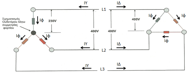
Suppose I connect two identical motors in the same network (next figure). Left in a star and right in a triangle.
 1) In the star connection we observe that while we apply to the motor polar voltage 400V, its coils are supplied with 230V. So the motor coils must be made to operate at a voltage of 230V.
In the triangle connection we observe that while we apply to the motor polar voltage 400V, its coils are also supplied with 400V. So the motor coils must be made to operate at a voltage of 400V.
2) In star wiring the current flowing through each winding of the motor Ιφ is equal to the current of the network ΙΥ, ie Ιφ = ΙΥ.
In the triangle connection the current flowing through each winding of the motor Ιφ is 1.73 times smaller than the current of the network ΙΔ, ie Ιφ = ΙΔ / 1.73
In star wiring the motor current is three times smaller than in triangle wiring, as shown below:

, in star wiring the motor will run normally but in triangle wiring they will be damaged immediately due to higher voltage.
Which motors can be connected to a star triangle switch
To connect a three-phase motor to the mains, the polar mains voltage must coincide with one of the operating voltages of the motor, which are indicated on its label. The possibilities of connecting to the network are given in the table below (the voltage that can not be used is written in small letters).

In general, in order to connect an engine to a star in the PPC network, the plate of 230/400 ΔΥ or 400 Υ
must be indicated. D
From the above voltages the only motor that can be connected to a star-delta switch is the one indicated on the plate of 400D
To connect an engine to the PPC network in a star the sign must read:
230/400 or 230/400 D / Y or 400 VY
In old engines we will see that they indicate 220/380 DC / 380 VY
The reason is why the engine can be connected in one network, such as PPC, in one way (eg triangle), while in another network created by a generator or an Inverter can be connected to another
Let's take another example where the motor writes 400/690 D / Y
The first voltage 400 listed corresponds to the D connection If we have polar voltage (between two phases) as in the PPC network must connect the motor triangle.
The second voltage 690 listed corresponds to the wiring Y. That is, if we have a polar voltage (between two phases) 690V, as in the case of a generator, we must connect the motor to Astera.

We have winding connection: 415 Δ

Internal connection of three coils. Motor
Inside the three-phase motors there are three composite coils with ends (U1-U2, V1-V2, W1-W2) or (UX, VY, WZ).
We call them complex because they consist of other smaller ones that are connected to each other in series, in parallel or complex depending on the type of machine.


Suppose I connect two identical motors in the same network (next figure). Left in a star and right in a triangle.
In the triangle connection we observe that while we apply to the motor polar voltage 400V, its coils are also supplied with 400V. So the motor coils must be made to operate at a voltage of 400V.
2) In star wiring the current flowing through each winding of the motor Ιφ is equal to the current of the network ΙΥ, ie Ιφ = ΙΥ.
In the triangle connection the current flowing through each winding of the motor Ιφ is 1.73 times smaller than the current of the network ΙΔ, ie Ιφ = ΙΔ / 1.73
In star wiring the motor current is three times smaller than in triangle wiring, as shown below:

, in star wiring the motor will run normally but in triangle wiring they will be damaged immediately due to higher voltage.
Which motors can be connected to a star triangle switch
To connect a three-phase motor to the mains, the polar mains voltage must coincide with one of the operating voltages of the motor, which are indicated on its label. The possibilities of connecting to the network are given in the table below (the voltage that can not be used is written in small letters).

In general, in order to connect an engine to a star in the PPC network, the plate of 230/400 ΔΥ or 400 Υ
must be indicated. D
From the above voltages the only motor that can be connected to a star-delta switch is the one indicated on the plate of 400D
To thank the ELECTRICIANS of the 1st EPAS OAED THESSALONIKI for the amazing technological content and the wonderful articles they publish on their blog.