


 Industrial ones are distinguished, depending on their power or current interruption, in:
Disconnectors
Load
switches Power switches (automatic)
Engine start switches
The problem of coupling and disconnection
Coupling
The starting current passing temporarily (for times from ms to s) from the switch is a multiple of the nominal (1 - 20 IN)
Before closing mechanical circuit breaker gap breaks, arc and contact contacts wear
Disconnection There are always small or large inductors in circuits ⇒ Opening the contacts does not mean interrupting the circuit but creating an arc between the switch contacts
The circuit breaks when the current is zero
When zero current appears across the switch contacts voltage depends on the load (Redux voltage, restriking voltage or transient recovery voltage, transient recovery voltage)
high rate of returning voltage rate (rate of rise of restriking voltage, rrrv, kV / μs) may cause the gap between the contacts of the switch to break
The return voltage applied to the ends of the contacts of a switch immediately after disconnection shall not cause a break Quick cooling of the arc, calculation of the maximum value of the return voltage and its derivative: necessary for successful disconnection Induction circuits have a high rate of return voltage rise Capacitive circuits double the return voltage
Automatic Power Switches
The power switch (DI) in English terminology appears exclusively as Circuit-breaker . Circuit breakers are power switches (DC switches) that automatically open the circuit at a predetermined time if the circuit current they protect exceeds a predetermined value.
They protect against overload and short circuits and consist of:
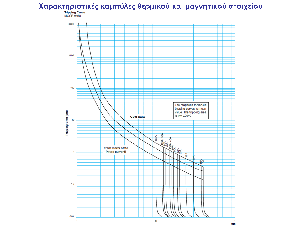
a thermal element or an HN that commands the DI to open (overload)
response time: seconds - minutes (depending on the current)
an EM element that commands the DI to open instantly (short circuit) ) response time: 10-100 ms, when the current exceeds a value ≅ 2 - 15 IN
Circuit breakers can be connected to HVs or surges for motor protection
Also circuit breakers are not used for operation

Closed and open type power switches
They are produced for rated currents from 16 A to 32 00A and are divided into sizes as shown in the pictures below.
Used in industrial panels to protect cables.
Used in industrial panels to protect cables.
For In up to 200A they are equipped with adjustable thermal and magnetic elements (thermomagnetic releases).
For In greater than 200A they are equipped with electronic protection units that allow us to precisely adjust the characteristic curves to achieve the correct selectivity.


Operating safety on MCCBs
One of the basic requirements of the standards mentioned in electrical materials is visual safety.
That is, the indication of the status of an MCCB, MCB should be clear.
That is, the indication of the status of an MCCB, MCB should be clear.
A power switch can take the following three positions
Position ON , their contacts are closed
OFF position , their contacts are open and this was done manually
TRIPPED position , their contacts are open and this was done automatically, ie the protection unit of the DI (eg thermal or magnetic) detected an error and ordered the contacts to be opened.
This is exactly what the image below shows.

The direction of the current is best the side of the electrical source to be below or above as shown in the image below.
This generally applies to all switches.
This generally applies to all switches.
Caution !!! If the MCCB is equipped with a low voltage relay then the power supply should be connected on the correct side.

Undervoltage trip coil

Used in very special cases. For example, in the MCCB which is on the secondary of the M / S 20000 / 400V, we ALWAYS add a low voltage coil so that it cannot close if no voltage comes from the secondary of the M / S. On the contrary, if this trend is lost, the MCCB automatically disconnects. This way we avoid the possibility for the M / S to work in reverse, ie for the voltage to pass (for any reason) from the low one and to be transformed to 20000V during the maintenance of the M / S.
Shunt trip coil

We encounter it when we want to remotely order the MCCB . We ALWAYS find it in the MCCB which is located in the secondary of the M / S 20000 / 400V and takes the command of automatic disconnection from the thermometer of the M / S. To order it we need to know the auxiliary voltage we have in the substation eg 100 VDC Note that the MCCB coupling command from a distance is rare and we avoid it for accident avoidance reasons . But if required, then we must supply the MCCB with a motor that will arm it (ie it will stretch the coupling spring)
The working coil allows us to close the DI with the help of an electric command. The operation of the coil is guaranteed if its operating voltage is between 80% and 110% of the rated auxiliary voltage
MCCB variants
In the image below we see the three basic variants of MCCBs.
Fixed type . It is the most common and obviously the most economical variant of MCCBs.
Plug-In . The MCCB consists of two parts, the mobile and the fixed. The craftsman electrician, with the help of a simple tool can remove it from its base.
We meet them in critical industrial facilities where production is not allowed to be interrupted to replace an MCCB.
We meet them in critical industrial facilities where production is not allowed to be interrupted to replace an MCCB.
Drawer (Withdrawable) . The MCCB is on a stretcher and can take 3 distinct positions, ON-OFF-ISOLATED.
We meet them in special industrial facilities with special requirements for complete isolation of the machine supplied by MCCB.
We meet them in special industrial facilities with special requirements for complete isolation of the machine supplied by MCCB.


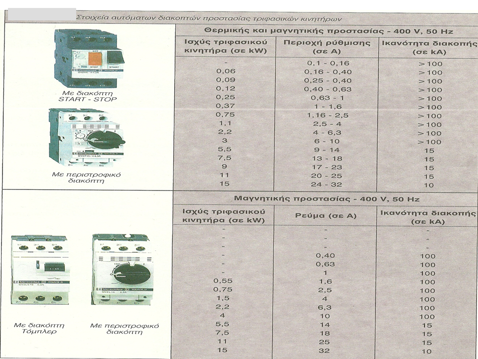
Motor protection switches (thermomagnetic switches) They are activated manually and provide protection to a motor:
-Against overloads, via thermal (adjustable),
-At short circuits, via magnetic.
Activation is done manually.
The thermomagnetic does the same job as the thermal but does not require a relay to control the motor which is done by the start and stop buttons.
The main difference with the thermal is the immediate interruption of the power supply without the need for an automation circuit.


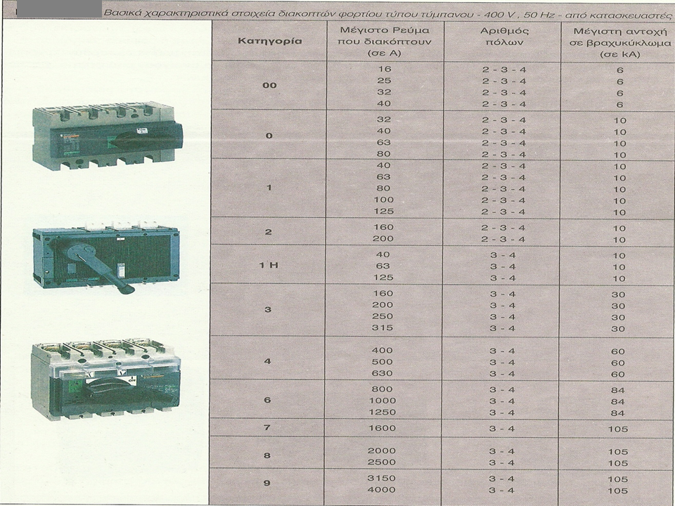
Load switches-Load switches-Safety circuit breakers - Pacco - Rotary load switches Load
switches are mechanisms used to manually shut down various power circuits of an installation and do not open in overload or short circuit.
Their dimensioning is based on the utilization Category required by the application and will be AC23 for control of inductive loads and motors or AC22 for mixed ohmic and inductive loads. Their nominal operating voltage should be 750 or 1,000 V (50/60 Hz), depending on the nominal voltage of the switch and be three-pole or four-pole. They must also comply with the requirements of the international standards IEC / EN 60947-1 and IEC / EN 60947-3.
The operating mechanism of the load switches should be quick make-quick break, solid construction, airtight to prevent access to the disconnect mechanism. The surface of the power contacts should be coated with silver, both to minimize their impedance and to protect them from corrosion. The housing should be made of insulating plastic material, designed to withstand demanding use without the risk of cracking or permanent deformation and with high impact resistance, for protection against falls. The terminals and exposed bare parts should be protected against accidental contact and have a degree of protection of IP 20.
Load switches with nominal intensity up to 125 A must be suitable for application in a DIN rail system (35mm), according to standard EN 60715. For nominal intensity from 160 A and above they must be suitable for mounting on a metal back panel .
Load switches must be operated by closing and opening manually, with the possibility of locking and a local control on their front. They must also be able to be fitted with a control panel and shaft to control the switch from a panel door, with a locking option for the safety of the operator (the panel door should only be opened if the load switch is OFF). All poles must be turned on and off at the same time. In the OFF position it must be ensured that all the contacts of the switches are open and have a visual indication of the position of the contacts via the control (ON, OFF).
Overload or short circuit protection should be provided by a forward circuit breaker with integrated thermomagnetic protection, as specified by the switch manufacturer. The load switches and the leading thermomagnetic protection switches must be of the same manufacturer in order to meet the conditions of cooperation (coordination) with each other.
Rated voltage
750 V AC (for rated current up to 125 A / AC21)
1,000 V AC (for rated current from 160 to 3.150 A / AC21) Insulated voltage (dielectric resistance) 6 kV (up to 125 A / AC21)10 kV (from 160 up to 2,500 A / AC21)8 kV (3,150 A / AC21) Rated short-term current ICW 0.5 kA (from 16 to 40 A / AC21 at 690 V / 1 sec.)1 kA (for 63 A / AC21 at 690 V / 1 sec.)1.5 kA (for 80 A / AC21 at 690 V / 1 sec.)2.5 kA (from 100 to 125 A / AC21 at 690 V / 1 sec.)15 kA (from 315 to 400 A / AC21 at 1,000 V / 1 sec.)20 kA (from 630 to 800 A / AC21 at 1,000 V / 1 sec.)50 kA (from 1,000 to 1,600 A / AC21 at 690 V / 1 sec.)
55 kA (from 2,000 to 2,500 A / AC21 at 690 V / 1 sec.)
80 kA (for 3,150 A / AC21 at 690 V / 1 sec.) 8 kA (from 160 to 250 A / AC21 at 1,000 V / 1 sec. .) Mechanical strength 20,000 handles (up to 250 A / AC21) 16,000 handles (from 315 to 250 A / AC21) 10,000 handles (from 630 to 800 A / AC21) 6,000 handles (from 1,000 to 2,500 A / AC21) 1,200 handles (3,150 A / AC21) Number of poles 3 or 4
Accessories
Load switches should be able to accept the following components: 4th pole for three-pole switches, auxiliary contacts, locking controls, extension shafts and control panels for panel door control.
Quality certification
The supplier must maintain an acceptable quality assurance system for products and services and demonstrate compliance with ISO 9001 certification, which is provided by an independent certified body. Load switches must be accompanied by a CE declaration of conformity.


Reblog https://oaedhlectrologoi.blogspot.com/

To thank the ELECTRICIANS of the 1st EPAS OAED THESSALONIKI for the amazing technological content and the wonderful articles they publish on their blog